

By Greg Washburn and Joshua Belisle · Edited by Dana Gardner
Published August 7, 2024 · Reviewed by Greg Washburn · August 3, 2026
Summary
Which conveying control do I need for my number of receivers?
The right conveying control depends mainly on how many receivers and pumps your system has. Fixed I/O controls cover systems from 1 receiver up to 34 receivers and 3 pumps. Expandable controls start with a main HMI panel and grow through expansion modules to as many as 120 receivers, adding options such as Auto ID source and destination proofing and silo monitoring.
Below are charts showing typical feature choices for Fixed I/O Controls and Expandable Controls. Simply click on the Maximum Number of receivers in your system (L.H. Column) and you will be linked to details about controls for that number of receivers.
| Fixed I/O Controls Features | |||||||||
| *Max# of Receivers | Max# of Pumps | **Proportioning | No-Load Alarm | Purge | Blowback | Ethernet Capability | Operator Interface | Power Voltage | I/O Voltage |
| 34 | 3 | ***Standard | Alarm/Light (Strobe Opt) | 10 | (16 or 32 Optional) | Optional | 5.7″ Color Touch Screen | 115 VAC 230 Opt. | 24 VDC 115 Opt. |
| 34 | 3 | ***Standard | Alarm/Light (Strobe Opt) | 10 | Optional | 4″ Monochrome Touch Screen | 115 VAC 230 Opt. | 24 VDC 115 VAC. | |
| 20 | 3 | ***Standard | Alarm/Light (Strobe Opt) | 8 | (16 Optional) | Optional | 5.7″ Color Touch Screen | 115 VAC 230 Opt. | 24 VDC 115 VAC |
| 20 | 3 | ***Standard | Alarm/Light (Strobe Opt) | 8 | (16 Optional) | Optional | 4″ Monochrome Touch Screen | 115 VAC 230 Opt. | 24 VDC 115 VAC |
| 10 | 2 | ***Standard | Alarm/Light (Strobe Opt) | 6 | (10 Optional) | Optional | 5.7″ Color Touch Screen | 115 VAC 230 Opt. | 24 VDC 115 VAC |
| 10 | 2 | ***Standard | Alarm/Light (Strobe Opt) | 6 | (10 Optional) | Optional | 4″ Monochrome Touch Screen | 115 VAC 230 Opt. | 24 VDC 115 VAC |
| 5 | 1 | ***Standard | Alarm/Light (Strobe Opt) | N/A | (5 Optional) | Optional | 4″ Monochrome Touch Screen | 115 VAC 230 Opt. | 24 VDC 115 VAC |
| 6 | 1 | Yes | (Horn/Light Opt) | N/A | N/A | N/A | Integrated LCD Screen | 115/230 | 24 VDC 115 Opt. |
| 5 | 1 | N/A | Horn Standard (Horn/Light Opt) | N/A | Yes | N/A | Integrated LCD Screen | 115/230 | 24 VDC 115 Opt. |
| 1 | 1 | 1 Prop or 1Purge Valve | Horn Standard (Horn/Light Opt) | 1 Prop or 1 Purge Valve | Yes | N/A | Integrated LCD Screen | 115/230 | 26 VDC 115 Opt. |
| 1 | 1 | N/A | (Horn/Light Opt) | N/A | Yes | N/A | Integrated LCD Screen | 115/230 | 27 VDC 115 Opt. |
| Note: # of receivers dependent on pump capacity and parameters of system design ** Proportioning can be added to any receiver with a proportioning valve and a separate control. *** Separate proportional settings may be made for each optional proportioning receiver within each pump system, but all valves int aht system are connected with a common signal. In operation, all proportioning valves within that pump system operate at the same time. | |||||||||
| Expandable Control Features | |||||||||||||
| *Max# Receiv- ers | Operator Interface | Receivers | Max# of Pumps | Purge Valves/Blowback | Proportion- ing | No-Load Alarm | *** AudioID Source | *** Audio ID Destination | Silo Monitor ing | Ethernet Capability | Power Voltage | I/O Voltage | |
| 120 | 10″ Color Touch Screen | 32 (Main HMI Panel) | 5 (Main HMI Panel) | 25 PurgeValves or Blowback (Main HMI Panel) | **Standard | Horn/ Light | Yes | 115 VAC | 24 VDC or 115 VAC. | ||||
| 120 | 6″ Color Touch Screen | 32 (Main HMI Panel) | 5 (Main HMI Panel) | 25 PurgeValves or Blowback (Main HMI Panel) | **Standard | Horn/ Light | Yes | 115 VAC | 24 VDC or 115 VAC. | ||||
| 104 | 6″ Color Touch Screen | 16 (Main HMI Panel) | 5 (Main HMI Panel) | 10 PurgeValves or Blowback (Main HMI Panel) | **Standard | Horn/ Light | Yes | 115 VAC | 24 VDC or 115 VAC. | ||||
| Options | Up to 4 Optional | Blowback Cards 16 BB/Card Up to 2 ea. (Factory Installed) | Alarm/ Strobe Optional | 5-Port Optional For Remote HMI | Optional 230 VAC | ||||||||
| Expan- sion Modules | Up to 11 Modules 8 Receivers/ Module | Up to 3 Modules 5 Pumps/ Module | Up to 3 Modules 16 Valves/ Module | Up to 16 Modules 16 Blowback/ Module | Up to 4 Modules 16 Sources/ Module | Up to 8 Modules 16 Destinations/ Module | Up to 3 Modules 4 Silos/ Module | ||||||
| For Main Panel w/32 Stations Up-To Totals/Funcation Based on Number of Modules Added | (32 Main Panel) Xpand to: 40,48,56,64, 72,80,88,96, 104,112,120 |
(5 Main panel) | (25 Main panel) Expand to: 40,56,72 | Opt. BB Cards 16 BB/card Up to 2 ea (Factory Installed) Expand to: 48,64,80,96,120 | Expand to: 32,40,48,56, 64,72,80, 88,96,104, 112,120 | Expand to: 16,32, 48,64 | Expand to: 16,32,48, 64,80, 96,112,128 | Expand to: 4-8-12 | |||||
| For Main Panel w/16 Stations Up-To Totals/Funcation Based on Number of Modules Added | (16 Main Panel) Expand to: 24,32,40,48, 56,64,72,80, 88,96,104 | (5 Main panel) Expand to: 10,15,20 | (10 Main panel) Expand to: 25,40,56,64 | Opt. BB Cards 16 BB/card Up to 1 ea for FXS-516 (Factory Installed) Expand to: 32,48,64, 80,96,104 | Expand to: 16,24,32, 40,48,56,64, 72-80,88, 96,104 | Expand to: 16-32- 48-64 | Expand to: 16,32,48, 64,80,96, 112,128 | Expand to: 4-8-12 | |||||
| Max Total/ Function | 104-120 Receivers | 20 Pumps | 64 Purge Valves | 104-120 Blowback | 104-120 Prop. Valves | 64 Sources | 128 Destinations | 12 Silos | |||||
| * Number of receivers dependent on pump capacity and system design. ** Separate proportional settings may be made for each optional proportioning receiver within each pump system, but all valves in that system are connected with a common signal. In operation, all proportioning valves within that pump system operate at the same time. Discreet proportioning is included for receivers wired to modules. ***Auto ID allows inputting of desired material source and destination information into the control, and the correct connection must be confirmed by the (optional) proofing connections at the manifold, or an alarm signal is generated and loading is not permitted. | |||||||||||||
Frequently Asked Questions
What is the difference between fixed I/O and expandable controls?
Fixed I/O controls come in set configurations, supporting from 1 to 34 receivers and up to 3 pumps. Expandable controls start with a main HMI panel handling up to 32 receivers and 5 pumps, then add expansion modules for more receivers, pumps, valves, blowback, sources, destinations, and silos, up to 120 receivers in total.
How does proportioning work across receivers on one pump?
Separate proportioning settings can be made for each optional proportioning receiver within a pump system, but all proportioning valves in that system share a common signal, so they operate at the same time. Proportioning can be added to any receiver with a proportioning valve and a separate control, and receivers wired to modules get discrete proportioning.
What does Auto ID do on a conveying control?
Auto ID lets you enter the desired material source and destination into the control. The correct connection must then be confirmed by optional proofing connections at the manifold. If the connection does not match, an alarm signal is generated and loading is not permitted, so the wrong material is not conveyed to the machine.
About the Authors

Vice President of Operations, Novatec
Greg Washburn is Vice President of Operations at Novatec and has been with the company for more than three decades. He is involved in all phases of engineering design and product manufacturing, giving him a broad perspective on how resin drying and conveying equipment moves from engineering concept through production and into real-world processing environments. Greg holds a B.S. in Mechanical Engineering from the University of Maryland, Baltimore County (UMBC) and an MBA from Loyola University Maryland. His experience spans engineering, manufacturing and operations across Novatec’s material-handling technologies.

Technology Manager, Novatec
Joshua Belisle is Technology Manager at Novatec, where his work focuses on simulation and technology development for resin drying. He earned a B.S. in Mechanical Engineering with a minor in Engineering Business from the University of Virginia in 2023 and joined Novatec that same year. Joshua uses simulation tools to investigate previously difficult-to-measure aspects of the drying process, helping Novatec better understand airflow, heat transfer and other variables that influence resin-drying performance.
Related Articles
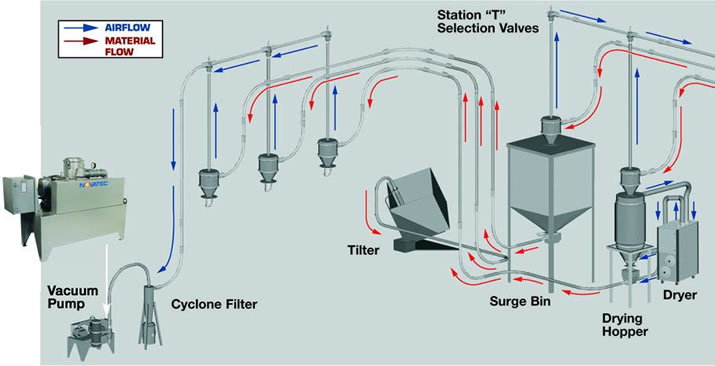
Review how dedicated material lines support loading, purging and material changes in a central conveying system.
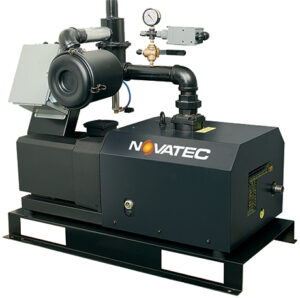
See how ultra high efficiency pumps support large resin throughputs and long conveying distances.

Compare vacuum receiver designs, filters and maintenance features when selecting a resin conveying system.
Ask the Expert